


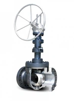

Fail-Safe Electric Ball Valve
Fail-Safe Electric Ball Valve
A fail-safe electric ball valve combines a quarter-turn ball valve with an electric actuator that uses stored energy to move the valve toward a predefined fail-safe position when a specified failure condition occurs.
Unlike a standard electric actuator that may remain in its last position after power loss, a fail-safe configuration is designed to perform a defined return action, subject to the actuator mechanism and operating conditions.
Key Selection Factors
- Fail-Safe Position: Select fail-open or fail-closed according to the process safety requirements.
- Failure Trigger: Specify whether the required action is triggered by power loss, control signal loss, or an emergency shutdown command.
- Actuator Torque: Verify that the actuator can operate the valve under the specified differential pressure and process conditions.
- Return Time: Define the required fail-safe travel time and confirm it for the selected valve-actuator assembly.
- Important: Power-loss response, signal-loss response, and emergency shutdown functions are separate requirements. Confirm each function during technical selection.
Technical Specifications
Available specifications depend on the valve model, actuator configuration, materials, and applicable design requirements.
|
Parameter |
Available Options / Selection Requirements |
|
Valve Type |
2-way or 3-way; L-port or T-port where applicable |
|
Nominal Size |
DN/NPS; confirm available sizes by model |
|
Pressure Rating |
PN or ASME Class; confirm pressure-temperature limits |
|
Body Material |
Carbon steel, stainless steel, duplex stainless steel, subject to availability |
|
Seat Material |
PTFE, RPTFE, PEEK, or metal seat, subject to service conditions |
|
Fail-Safe Action |
Fail-open or fail-closed |
|
Stored-Energy Mechanism |
Spring return or electrical energy storage, depending on actuator design |
|
Power Supply |
Confirm rated voltage, AC/DC type, and frequency |
|
Control Mode |
On/off or modulating, where supported |
|
Control Signal |
Confirm available inputs, such as 4–20 mA or 0–10 V for compatible modulating models |
|
Protection Rating |
Specify the required IP rating and environmental conditions |
|
Hazardous-Area Requirements |
Confirm applicable ATEX/IECEx certification for the exact configuration |
|
Functional Safety |
Confirm documented SIL capability and suitability for the intended safety function |
|
End Connections |
Threaded, flanged, welded, or sanitary connections, subject to model availability |
|
Return Time |
Specify target fail-safe travel time for technical verification |
Applicable Standards
The following standards may be relevant depending on the selected valve design, connections, testing requirements, and installation environment.
Valve Design: API 608, ISO 17292, or ASME B16.34, where applicable.
Dimensions and Connections: ASME B16.10, ASME B16.5, EN 558, or EN 1092-1, as applicable.
Pressure Testing: API 598 or the specified applicable test standard.
Fire-Safe Design: API 607 or ISO 10497, where the valve design is qualified.
Actuator Mounting and Enclosure Protection: ISO 5211 and IEC 60529, respectively, where applicable.
Compliance must be verified against the actual product design and supporting documentation. Listing a standard does not establish that every configuration complies with it.
Fail-Safe Options & Engineering Selection
Fail-Open vs. Fail-Closed
- Fail-Open: Moves the valve toward the open position under the specified failure condition. It may suit applications requiring continued circulation, subject to system safety analysis.
- Fail-Closed: Moves the valve toward the closed position to isolate a line when required by the process safety strategy.
- Application-Specific Selection: The appropriate fail position depends on fluid hazards, equipment protection, process response, and the consequences of loss of flow or isolation.
Failure Triggers & Return Performance
- Power Loss: Confirm whether the actuator can complete the required return movement using its stored energy.
- Signal Loss: Verify whether signal failure initiates a return action or requires separate control logic.
- Emergency Shutdown: Confirm the required command interface, response sequence, and any associated safety-system requirements.
- Return Time & Torque: Validate the specified travel time against valve torque, differential pressure, and actuator operating limits.
Applications
Typical Application Areas
Chemical Process Lines: Automated isolation or flow-path control, subject to media compatibility and the process safety assessment.
HVAC & Cooling Systems: Fail-safe positioning in selected circulation, bypass, or isolation circuits.
Water & Wastewater Treatment: Automated valve positioning in treatment, dosing, and filtration systems where compatible with the process.
OEM Equipment & Skid Packages: Integration into packaged systems requiring a defined valve response under specified failure conditions.
Application suitability must be confirmed against operating pressure, temperature, fluid properties, required flow conditions, and the system's safety design.
Manufacturing & Quality Verification
Product Verification
Pressure Testing: Confirm the applicable shell and seat leakage tests and acceptance criteria.
Material Traceability: Request material certificates and heat or batch traceability where required.
Fail-Safe Function Testing: Verify the specified trigger, return direction, and travel time for the supplied configuration.
Documentation: Request applicable test reports, inspection records, drawings, and certificates for the ordered assembly.
Testing scope and documentation availability should be agreed upon before order confirmation.
Customization & RFQ Requirements
Provide the following information to support technical selection and quotation.
Valve & Process Conditions
- Valve Specifications: DN/NPS, pressure rating, body material, seat material, and end connection.
- Operating Conditions: Fluid composition, minimum and maximum temperatures, operating pressure, and maximum differential pressure.
- Valve Requirements: Two-way or three-way configuration, required flow path, and any leakage acceptance criteria.
Actuator & Project Requirements
- Fail-Safe Logic: Fail-open or fail-closed, triggering conditions, and target return time.
- Electrical Requirements: Supply voltage, control mode, input signals, and enclosure protection.
- Safety & Compliance: Applicable hazardous-area requirements, functional-safety requirements, and required certificates.
- Order Details: Quantity, delivery destination, required documentation, and target delivery schedule.
Technical selection should be confirmed before finalizing the valve-actuator combination.
Frequently Asked Questions
Q: What is the difference between a fail-safe and a standard electric ball valve?
A: A standard electric actuator may remain in its last position after power loss. A fail-safe configuration uses a suitable stored-energy mechanism to move the valve toward a defined position when the specified trigger occurs. The actual response depends on the actuator design.
Q: How do I choose between fail-open and fail-closed?
A: Choose according to the consequences of losing flow or failing to isolate the line. Evaluate fluid hazards, equipment protection, process conditions, and the overall safety strategy before selecting the fail position.
Q: Does the valve automatically return to its safe position when the control signal is lost?
A: Not necessarily. Signal-loss response depends on the actuator controls and configuration. Specify signal-loss behavior separately from power-loss behavior and confirm it in the technical documentation.
Q: How is the required fail-safe return time determined?
A: Return time depends on the actuator mechanism, valve torque requirements, stored-energy capacity, and operating conditions. Specify the required travel time and verify it under the intended operating conditions.
Q: Does fail-safe operation guarantee ATEX or SIL compliance?
A: No. Fail-safe operation, explosion protection, and functional safety are distinct requirements. Confirm the relevant certificates, documented safety capability, and suitability of the complete configuration for the intended application.
Technical Resources & RFQ Support
Technical Datasheets: Request model-specific specifications, operating limits, and actuator details.
Dimension Drawings & CAD Models: Request available 2D drawings and 3D files for installation review.
Engineering Selection: Submit operating conditions, valve requirements, fail-safe logic, and electrical specifications for technical evaluation.
Hot Tags: fail-safe electric ball valve, China fail-safe electric ball valve manufacturers, suppliers
Previous
No InformationYou Might Also Like
Send Inquiry